- 您现在的位置:买卖IC网 > Sheet目录2040 > PI74ST1G125TEX (Pericom)IC BUFF TRI-ST HI SPEED SOT23-5
3
PS8521I
12/02/09
PI74ST1G125
SOTiny Gate ST
Buffer with 3-State Output
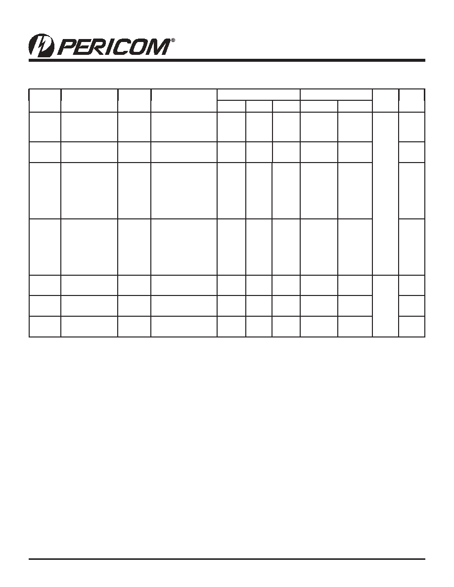
AC Electrical Characteristics
Symbol
Parameter
VCC(V)
Conditions
TA = +25C
TA = -40 C to +85C
Units
Fig.
No.
Min.
Typ.
Max.
Min.
Max
tPLH
tPHL
Propagation
Delay
1.8
2.5±0.2
3.3±0.3
CL = 15pF,
RL = 1MΩ
2.0
0.8
0.5
2.8
1.8
1.3
3.7
2.5
2.0
0.8
0.5
4.1
2.8
2.2
ns
1
3
tPLH
tPHL
Propagation
Delay
3.3±0.3
CL = 50pF,
RL = 500Ω
1.5
2.6
3.4
1.5
3.7
1
3
tPZL
tPZH
Output Enable
Time
1.8
2.5±0.2
3.3±0.3
CL = 50pF,
RD = 500Ω,
RU = 500Ω,
S1 = GND for tPZH
S1 = VIN for tPZL
VIN = 2 x VCC
2
1.5
5.8
4.1
3.1
7.5
5.4
4.1
2
1.5
8.3
5.9
4.5
1
3
tPLZ
tPHZ
Output Disable
Time
1.8
2.5±0.2
3.3±0.3
CL = 50pF,
RD = 500Ω,
RU = 500Ω,
S1 = GND for tPHZ
S1 = VIN for tPLZ
VIN = 2 x VCC
2
1.5
4.9
3.6
2.8
5.9
4.8
3.4
2
1.5
1.0
6.5
5.3
3.7
1
3
CIN
Input Capaci-
tance
VIN = 0
4
pF
COUT
Output Capaci-
tance
VIN = 0
8
CPD(1)
Power Dissipa-
tion Capacitance
3.3
17
2
Notes:
1.
CPD is dened as the value of the internal equivalent capacitance which is derived from dynamic operating current consumption (ICCD) at no
output loading and operating at 50% duty cycle (see Figure 2). CPD is related to ICCD dynamic operating current by the expression:
ICCD = (CPD)(VCC)(fIN) + (ICC static).
09-0007
发布紧急采购,3分钟左右您将得到回复。
相关PDF资料
PI74ST1G126CEX
IC BUFF TRI-ST HIGH SPEED SC70-5
PI74STX1G126TEX
IC BUFF TRI-ST HI SPEED SOT23-5
PI74STX2G4245ZEEX
IC 2BIT LVL SHFT BUF/TXRX 12TDFN
PI74VCX16244AEX
IC BUFF/DVR 3ST 16BIT 48TSSOP
PI74VCX16245AEX
IC TXRX 16BIT BIDIR 3ST 48TSSOP
PI74VCX16373AEX
IC 16BIT D TRANSP LATCH 48TSSOP
PK-12N40PEQ
BUZZER 3-15VDC 83DB PCB 4.1KHZ
PK-12N40PQ
BUZZER PIEZO 4.1KHZ 14MM PC MT
相关代理商/技术参数
PI74ST1G125TX
制造商:Pericom Semiconductor Corporation 功能描述:Buffer/Line Driver 1-CH Non-Inverting 3-ST CMOS 5-Pin SOT-23 T/R
PI74ST1G126CEX
功能描述:缓冲器和线路驱动器 Buffer w/ TriState Output RoHS:否 制造商:Micrel 输入线路数量:1 输出线路数量:2 极性:Non-Inverting 电源电压-最大:+/- 5.5 V 电源电压-最小:+/- 2.37 V 最大工作温度:+ 85 C 安装风格:SMD/SMT 封装 / 箱体:MSOP-8 封装:Reel
PI74ST1G32CEX
功能描述:逻辑门 2 Input or Gate RoHS:否 制造商:Texas Instruments 产品:OR 逻辑系列:LVC 栅极数量:2 线路数量(输入/输出):2 / 1 高电平输出电流:- 16 mA 低电平输出电流:16 mA 传播延迟时间:3.8 ns 电源电压-最大:5.5 V 电源电压-最小:1.65 V 最大工作温度:+ 125 C 安装风格:SMD/SMT 封装 / 箱体:DCU-8 封装:Reel
PI74ST1G32TEX
功能描述:逻辑门 2 Input or Gate RoHS:否 制造商:Texas Instruments 产品:OR 逻辑系列:LVC 栅极数量:2 线路数量(输入/输出):2 / 1 高电平输出电流:- 16 mA 低电平输出电流:16 mA 传播延迟时间:3.8 ns 电源电压-最大:5.5 V 电源电压-最小:1.65 V 最大工作温度:+ 125 C 安装风格:SMD/SMT 封装 / 箱体:DCU-8 封装:Reel
PI74ST1G32TX
制造商:Pericom Semiconductor Corporation 功能描述:
PI74ST1G86CEX
功能描述:逻辑门 2 Input XOR Gate RoHS:否 制造商:Texas Instruments 产品:OR 逻辑系列:LVC 栅极数量:2 线路数量(输入/输出):2 / 1 高电平输出电流:- 16 mA 低电平输出电流:16 mA 传播延迟时间:3.8 ns 电源电压-最大:5.5 V 电源电压-最小:1.65 V 最大工作温度:+ 125 C 安装风格:SMD/SMT 封装 / 箱体:DCU-8 封装:Reel
PI74ST1G86CX
制造商:Pericom Semiconductor Corporation 功能描述:
PI74STX1G00CX
功能描述:IC SINGLE 2-IN NAND GATE SC70-5 RoHS:否 类别:集成电路 (IC) >> 逻辑 - 栅极和逆变器 系列:74STX 标准包装:2,000 系列:74LCX 逻辑类型:逆变器,缓冲器 电路数:1 输入数:8 特点:三态 电源电压:2 V ~ 3.6 V 电流 - 静态(最大值):10µA 输出电流高,低:24mA,24mA 逻辑电平 - 低:0.7 V ~ 0.8 V 逻辑电平 - 高:1.7 V ~ 2 V 额定电压和最大 CL 时的最大传播延迟:6.5ns @ 3.3V,50pF 工作温度:-40°C ~ 85°C 安装类型:表面贴装 供应商设备封装:20-SSOP 封装/外壳:20-SSOP(0.209",5.30mm 宽) 包装:带卷 (TR)